|
| Communication signals | A (+ Tx/Rx), B (- Tx/Rx), GND |
| Protection | overvoltage protection TVS 600W |
| Terminating resistors | A 1kΩ to +5V, B 1kΩ to GND, between A & B 120Ω - JUMPER |
| Galvanic separation | 1kV from M-Bus line |
| Connector | terminal block with plug-in connector for wires of up to 2.5 mm2 cross-section area |
|
| Number of devices that can be connected | 1 to 4 SLAVE devices, idle current max. 6 mA |
| Baud rate | 300 - 9600 bps |
| Protection | - overvoltage protection TVS 600W |
- electronic protection against overloads and short circuit on the communication line |
note: converter can withstand sustained short circuit on the communication line |
| Galvanic separation | 1kV from power supply and from RS485 line |
| Connector | terminal block with plug-in connector for wires of up to 2.5 mm2 cross-section area |
|
| Recommended range of power supply voltages |
| DC power supply | 7V to 28V |
| Maximum limits of supply voltage - permanent operation at these voltages is not recommended |
| Minimum DC power | 6.5V - minimal voltage necessary for the operation of the converter |
| Maximum DC power | 30V - above this the overvoltage protection will activate |
| Protection | - overvoltage protection TVS 600W |
| Power consumption | 0.3W to 1W. Depends on M-Bus line load and power supply. |
| Connector | terminal block with plug-in connector for wires of up to 2.5 mm2 cross-section area |
|
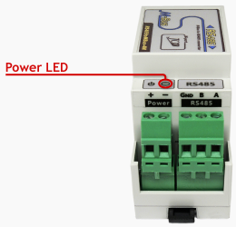
| Power - green | indication of connected supply voltage |
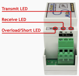
| Transmit - green | indication of data broadcasting on the M-Bus line |
| Receive - yellow | indication of data reception on the M-Bus line |
| Overload/Short - red | indication of M-Bus line overload – flashing (idle current > 8mA) |
| indication of short on the M-Bus line – turned on (resistance of the line < 500Ω) |
|
| Operating range | -20°C to 70°C |
|
| Mechanical design | plastic box |
| Mounting | 35 mm DIN rail (EN 50022 top hat rail) |
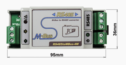
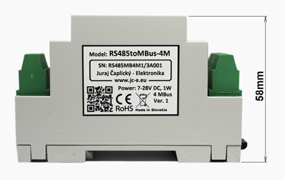
| Dimensions: height x width x length | 58 x 36 x 95 mm |
| Protection classification | IP20 |
| Weight | 70g |
EMC compatibility of the M-Bus converter has been tested according to the following industrial environment standards.
|
| Standard | Test | Level |
| EN 55011 | Power line - CONDUCTED EMISSIONS 10/150 kHz - 30 MHz | Class A |
| EN 55011 | RADIATED EMISSIONS (Electric Field) 30 MHz - 1000 MHz | Class A |
| |
|
| Standard | Test | Level |
| EN 61000-4-2 | ELECTROSTATIC DISCHARGE (ESD) - Contact discharge | ± 4 kV |
| EN 61000-4-2 | ELECTROSTATIC DISCHARGE (ESD) - Air discharge | ± 8 kV |
| EN 61000-4-4 | ELECTRICAL FAST TRANSIENT/BURST - Power line | ± 4 kV |
| EN 61000-4-4 | ELECTRICAL FAST TRANSIENT/BURST - M-Bus, RS485 line | ± 4 kV |
| EN 61000-4-5 | SURGE IMMUNITY - Power line. Common/differential mode. | ± 1 kV / ± 0.5 kV |
| EN 61000-4-5 | SURGE IMMUNITY - M-Bus, RS485 line. Cable shielding. | ± 4 kV |
| EN 61000-4-5 | SURGE IMMUNITY - M-Bus line. Common/differential mode.* | ± 2 kV / ± 1 kV |
| EN 61000-4-6 | CONDUCTED DISTURBANCES, INDUCED BY RADIO-FREQUENCY | 10 V |
| FIELDS 0.15MHz - 80 MHZ. Power line and M-Bus line. |
* test carried out at the request of the manufacturer.
The M-Bus port has an increased durability against overvoltage. Carrying out this type of test is not required with the use of shield cable.
